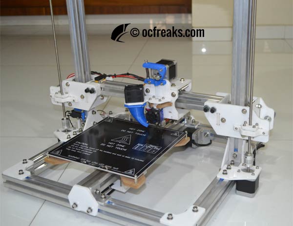
In Chapter 1 of the DIY 3D printer build, we had explained all the hardships we faced in our Prusa i3 build, and how it motivated us to build our own DIY 3D printer. In this chapter, we will be detailing the structure of our printer.
The 3D printer that we decided to build was a Cartesian-XZ Head FDM type.
The first and foremost thing we needed to think about for our DIY 3D Printer build was the body/structure. Any machine is only as good as the structure that supports it, so we didn’t take this lightly.
We tackled this issue step by step.
Open-Air design or an Enclosed Chassis design
Both these designs have their own sets of advantages and disadvantages:
| Open-Air Type | Enclosed-Chassis Type |
|---|---|
| Cheap. Only require the material for skeleton support. | Expensive. Need to decide on the chassis material as well, increasing costs by a lot. |
| Simple to design and assemble. | Design and assembly both are more complicated. |
| Debugging and Troubleshooting is much easier | Debugging and troubleshooting becomes much more of a hassle as the chassis needs to be dismantled to fix even the smallest issues |
| Looks incomplete. Not as aesthetically pleasing. | More aesthetically pleasing, when done nicely, that is. |
| Printing in ABS is harder | Aids printing in ABS by a (teensy-weensy) bit. |
In the end, we decided to go with an open-air design as we found it most suitable for our scenario.
Structure Material
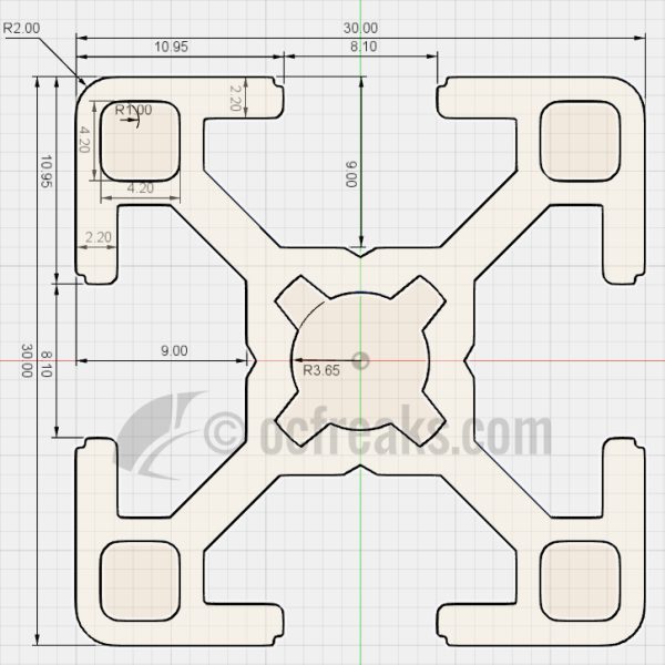
The next thing we needed to tackle was what to use for skeleton support structure. The things we initially considered were: aluminium angles and Aluminium square/rectangular profiles. Both these required heavy labour on our part to make the structure (Drilling Holes in multiple places, etc.). Luckily we found a local seller who was willing to sell us 30×30 Aluminium extrusions(T-Slot profiles) at a reasonable rate. This helped us in more ways than one, as you will come to know in our later posts.
However, the seller was selling T-Slot nuts and angle brackets at exorbitant prices. This created a whole new set of problems for us to tackle.
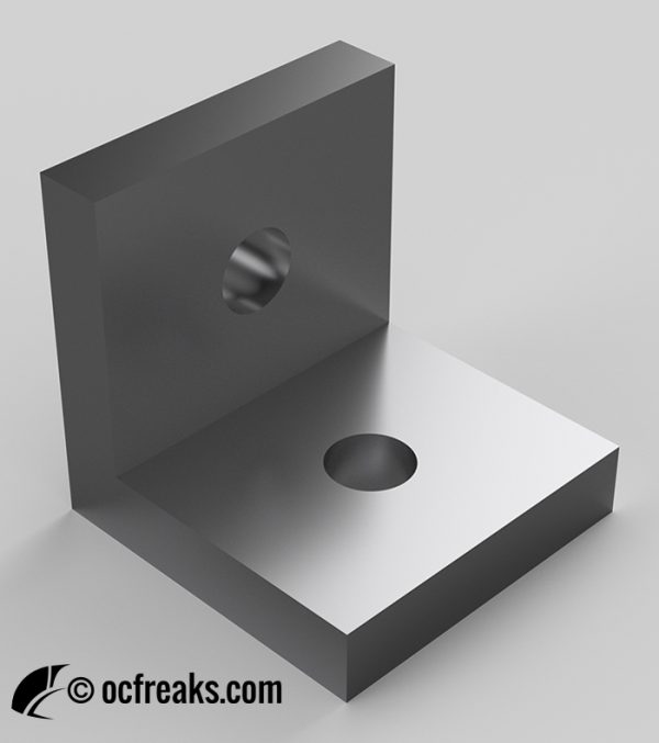
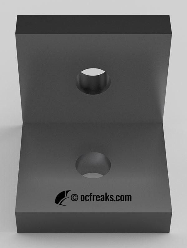
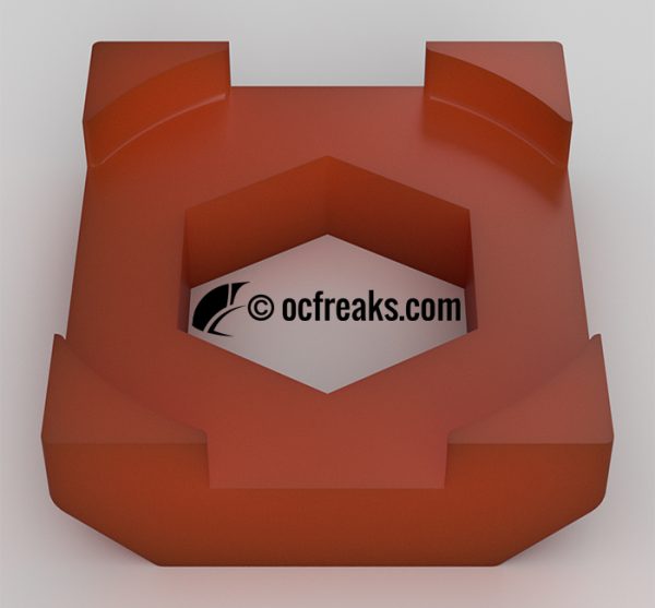
The angle brackets, we figured, could just as well be substituted with precise aluminium angles cut at exact lengths (25mm), with holes drilled in them. But What about the T-Slot nuts. After brainstorming for quite a bit, we figured out a way. We already had (albeit, a horrible excuse for) a 3D printer (read chapter 1). So we designed a 3D model with shape and dimensions such that it could slide inside the slot of the extrusion and with holes cut out to fit a 5mm nut and a DIN 9021 M6 washer. We printed said part, fit the nut and washer in it part and fixed them there semi-permanently using Super-Glue. Voila, we made our own 3D-Printed T-Slot nut!!!We worked out how much this cost. Turns out, it was a hell of a lot cheaper(even with all the labour and material counted in) than the price of the T-Slot nut. We still had to use (actual) T-Slot Nuts in places with tight tolerances, but that just amounted to 8. All in all we required about a 100 T-Slot Nuts, a far cry from what we actually used.
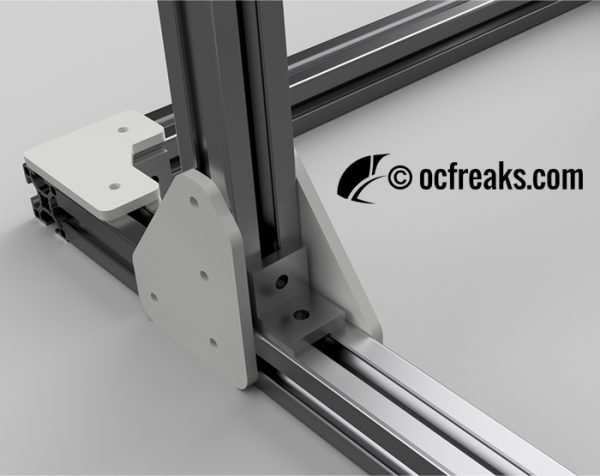
Have a look at the images of our DIY Brackets and T-Slot Nuts:
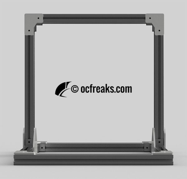
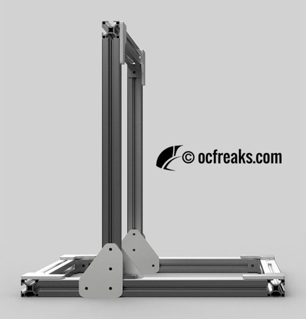
With all that being settled, we started on the base design of the skeleton structure. Here’s a few rendered images of the same:
Discover more from OCFreaks!
Subscribe to get the latest posts sent to your email.

