Project Bootstrap – (Yet another xD) DIY 3 Axis CNC
Project Bootstrap is OCFreaks’ 2nd Official Project which is – a Homemade DIY CNC Routing and Milling Machine.
For those guys who are new to CNC and related stuff lemme give you a formal introduction to ‘CNC Machine’ :
Link to CNC on wiki : http://en.wikipedia.org/wiki/Numerical_control
It all started when I entered into Robotics & Embedded – Somewhere around in late 2009. Back then I was working on a Hexapod Robot project. I had made a new design for my hexapod and then was faced with a challenge. How do I cut the design ? I had to do it manually or get it fabricated. Pro fabricators wont accept such sample quantity jobs. So I had to manually cut the parts for my hexapod .. Damn! During that time a random thought came in my mind – Why not make a CNC router and cut parts for robotics projects at home? I was like .. hmmmmm .. but making a CNC is tough ask. For months I was still like .. hmmmmm .. can I make it? can I really make it? Finally in April 2012 somewhere around my birthday I decided – Enough of this ‘can I make it? crap’ , Lets start freaking buildin’ it. After my exams in June 2012 I started researching on DIY CNCs seriously .. I mean damn seriously .. endlessly going through CNC related stuff for hours n hours n hours. My CNC story starts from here! My CNC project is divided into Intervals – each interval has its own story to say.
Interval 2 : Part Selection and Sourcing
Interval 2B : LM Bearings , Couplings & Motor Selection
Interval 3 : The Design**
Interval 4 : Ze Assembly & Electronics
Interval 4B : Ze Custom Electronics
Interval 5 : Final Calibration**
Interval 6 : PCB Engraving Test**
Interval 7 : …In Progress…**
Note : ‘**’ => Post has not been uploaded yet. It will be online soon.
Here is Quick Video of Interval 6 : Here I’ve used the CNC to engrave text on PCB Copper Clads:
So .. What next in pipeline? : 2nd Version of the current CNC and a 3D-Printer!
The CNC Build in a Nutshell(sort-of)
6mm Thick Wooden Plates cut as per Design:
Drilled Sandwiched plates with effective thickness of 12mm:
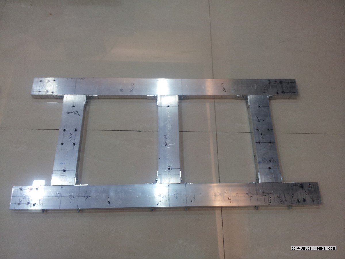
Base aluminum frame:
Anti-backlash Lead Nuts , Regular ball-Bearings , Thrust Bearings & Couplings , Shaft and Lead Screw end support blocks:
Cut & Drilled Aluminum Angles of thickness 2mm:
Open and Closed type Linear Motion Bearings for Linear Motion:
Nema-23 18.9Kgcm Stepper Motors:
20mm Shafts , M10x1.5 Mild-steel & Stainless-steel Lead Screws:
Fasteners:
1st Prototype of Opto-Isolated Parallel Breakout Board – Sadly this prototype failed and didn’t make it ): [2nd Prototype in Progress (:]
2nd Prototype of DRV8825 based stepper motor driver – This too didn’t make it since it had a few bugs ): [3rd Prototype in Progress (:]
5mm Thick Aluminum Angles for reinforcement:
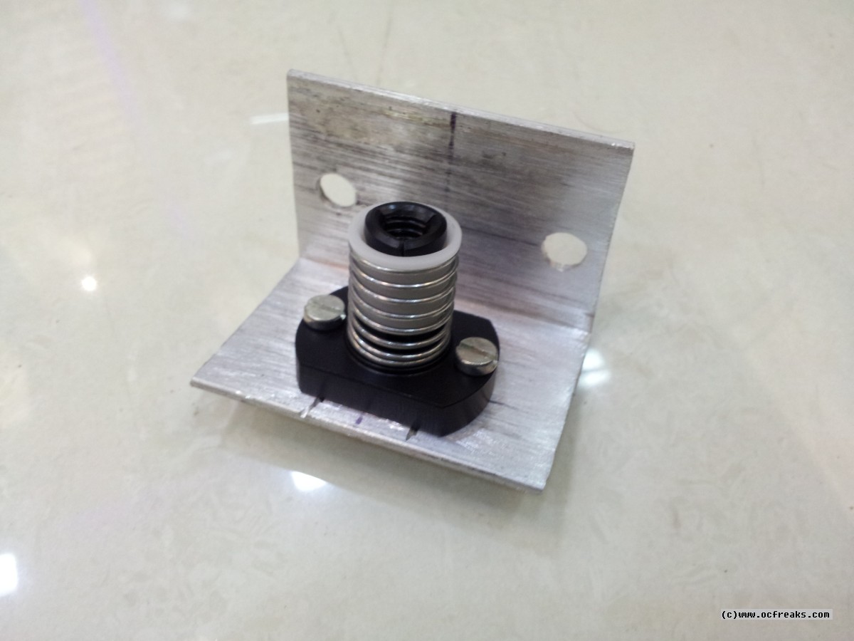
Anti-backlash Lead Nut Housing:
Lead Nut where it should be: When the Lead Screw rotates the Lead Nut moves back-n-forth i.e it converts the rotational motion of stepper motors into linear motion.
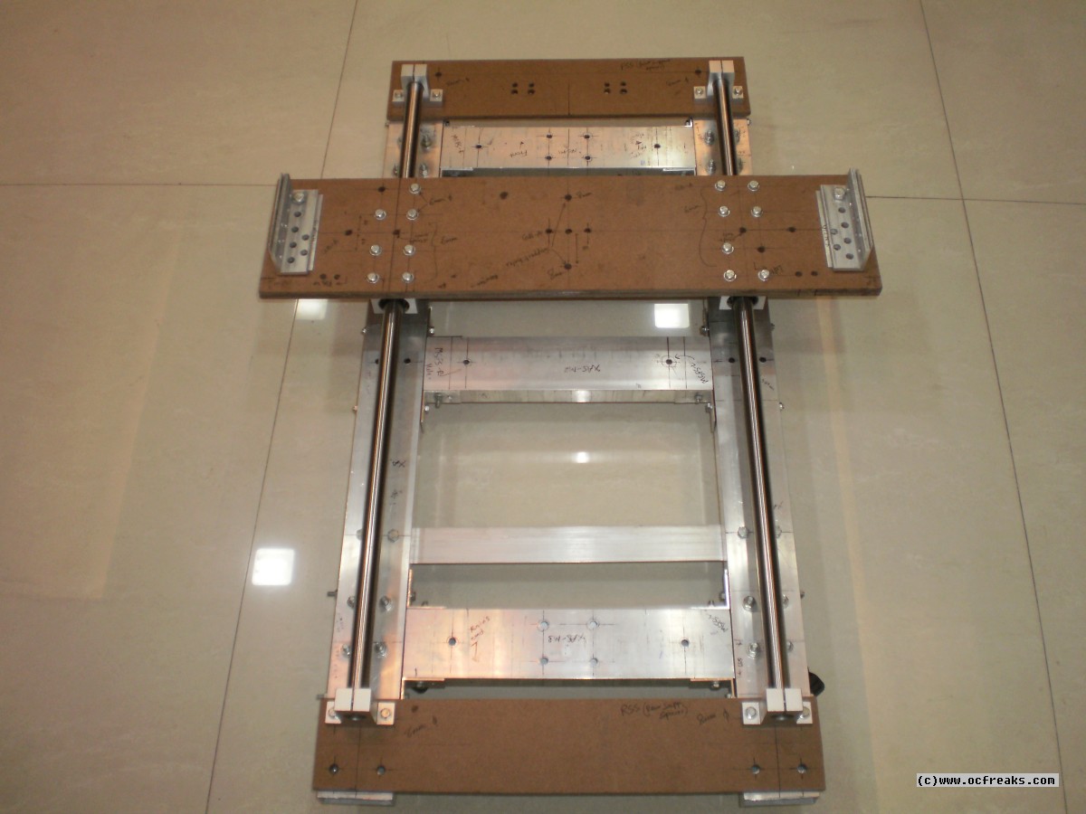
X-axis Base on which Z-axis base is mounted:
Y-axis Base:
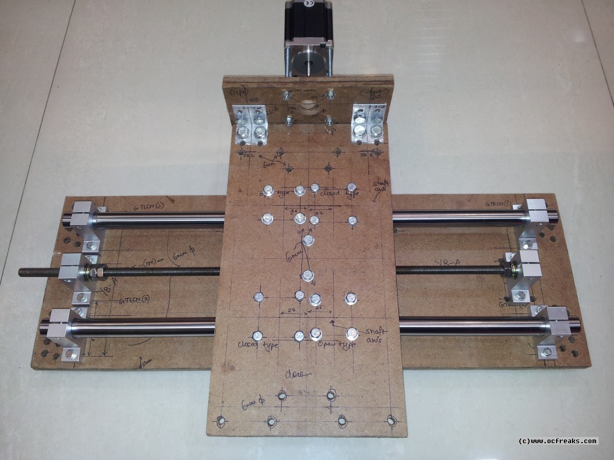
Z-axis Base :
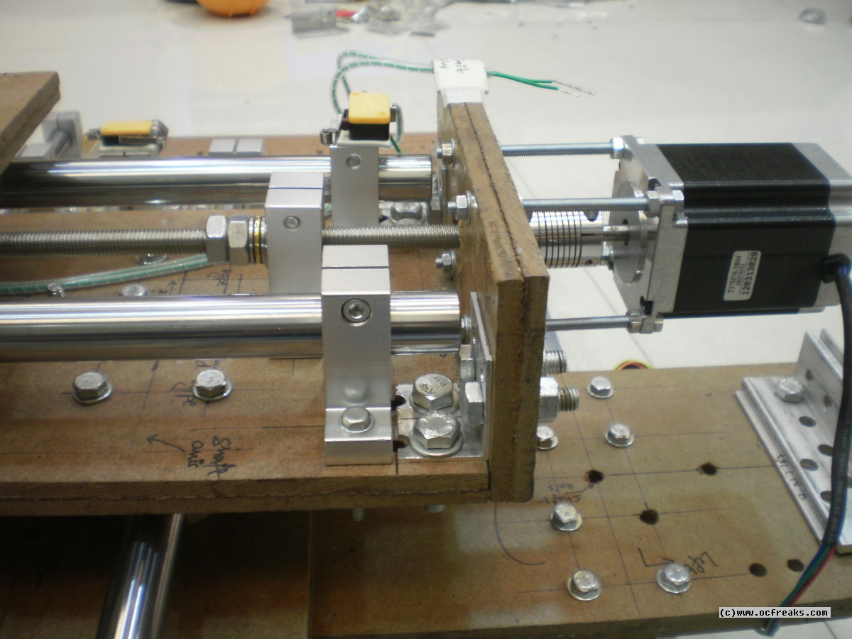
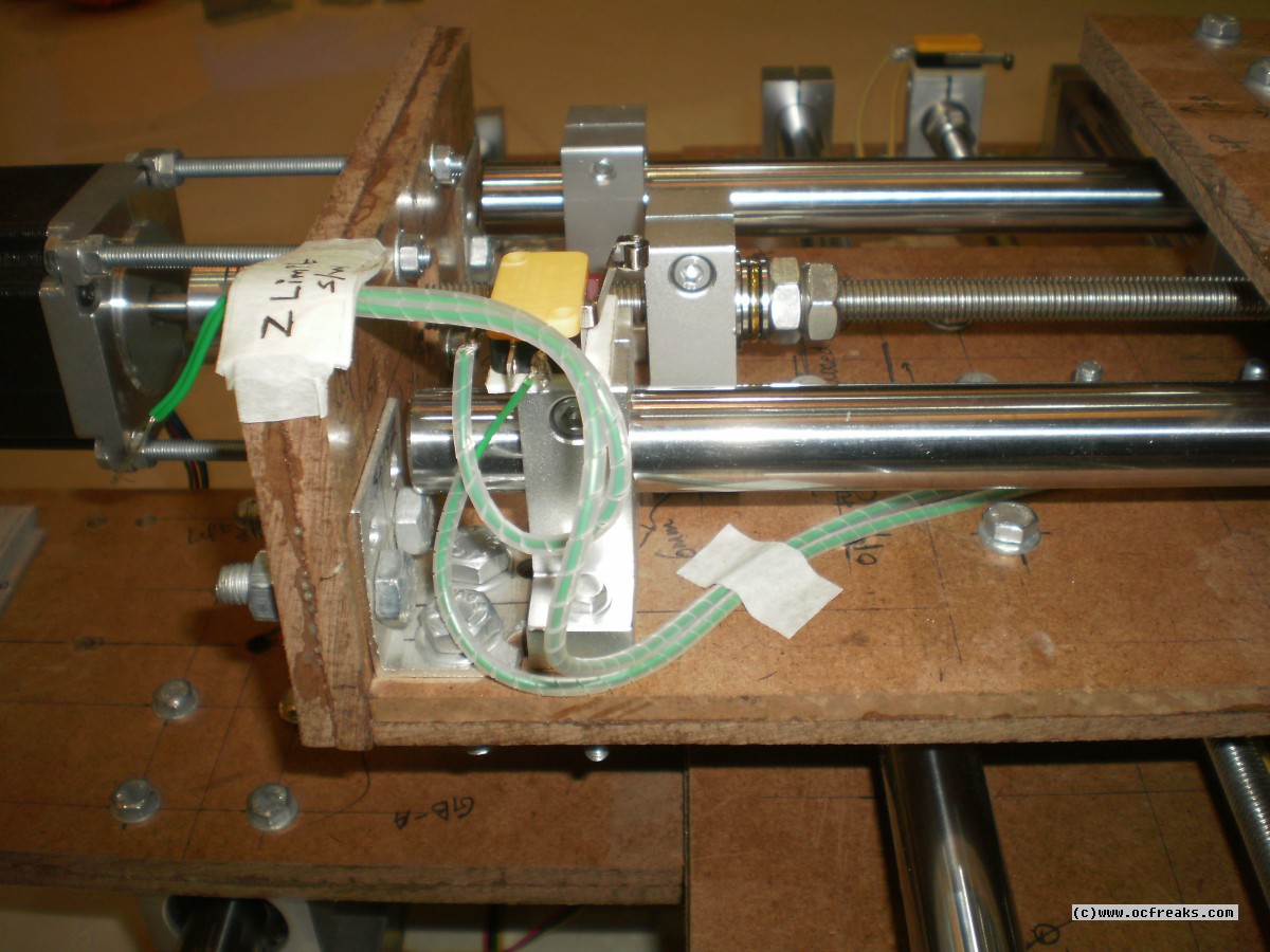
Z-axis Lead Screw Assembly:
Thrust Bearings to secure Lead Screws in place:
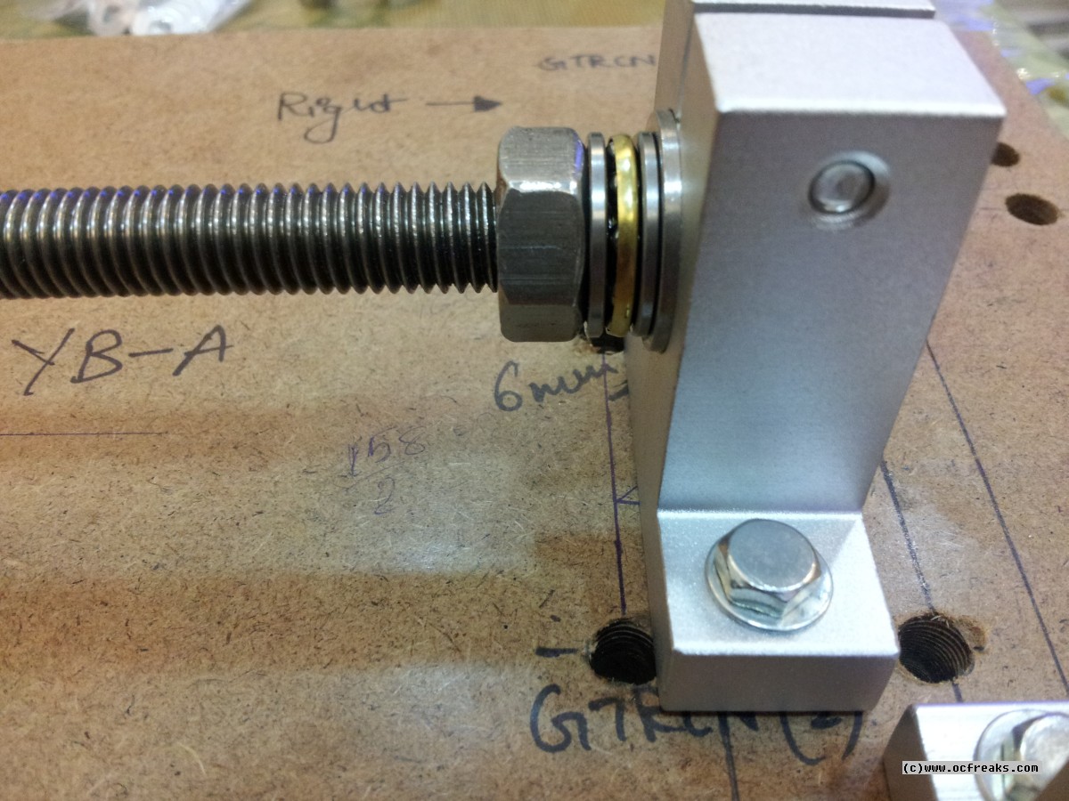
Z-axis Assembly:
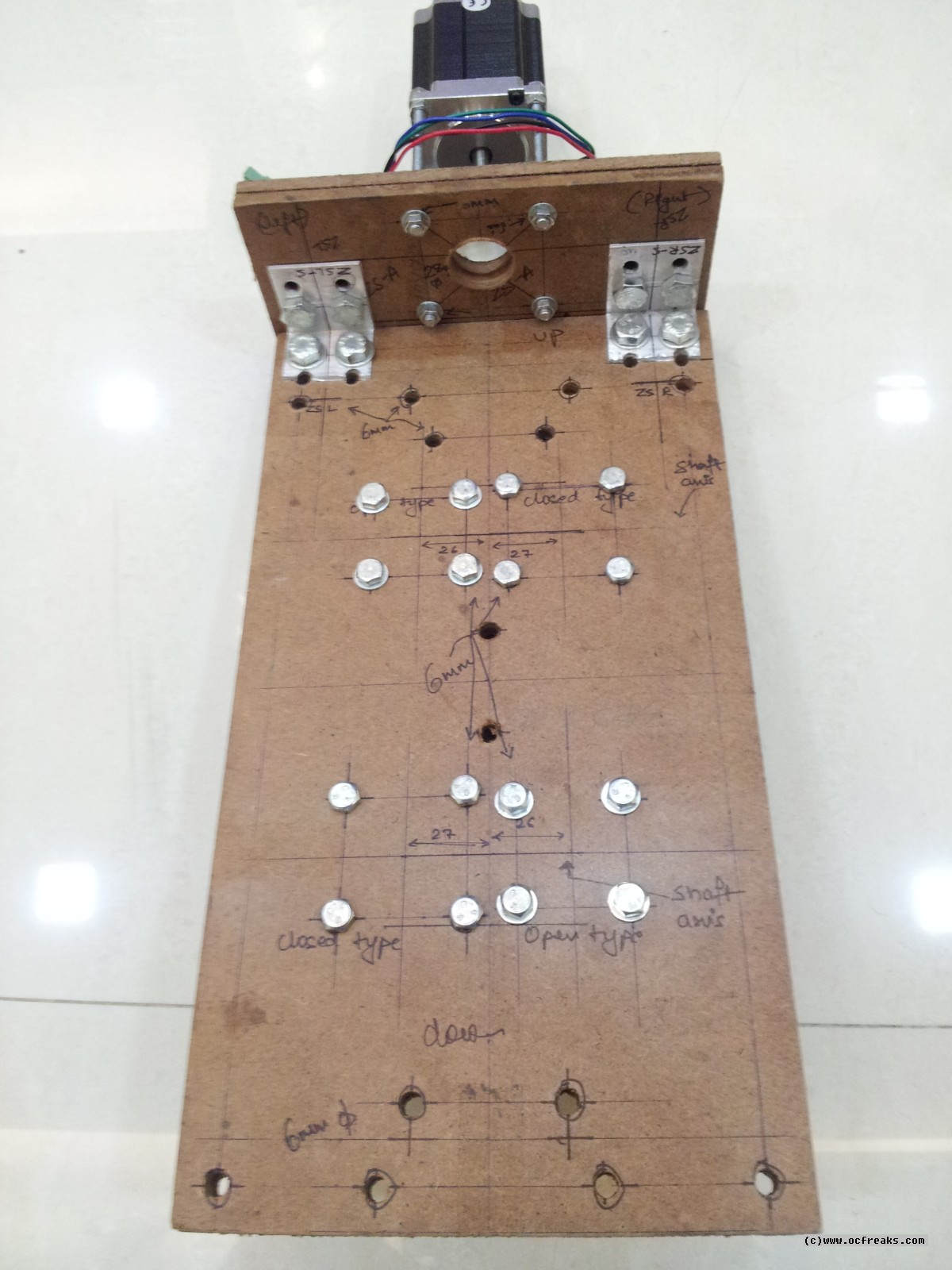
Z-axis Stepper Motor:
Y-axis Stepper Motor:
X-axis Stepper Motor:
Y-axis Limit/Home Switches:
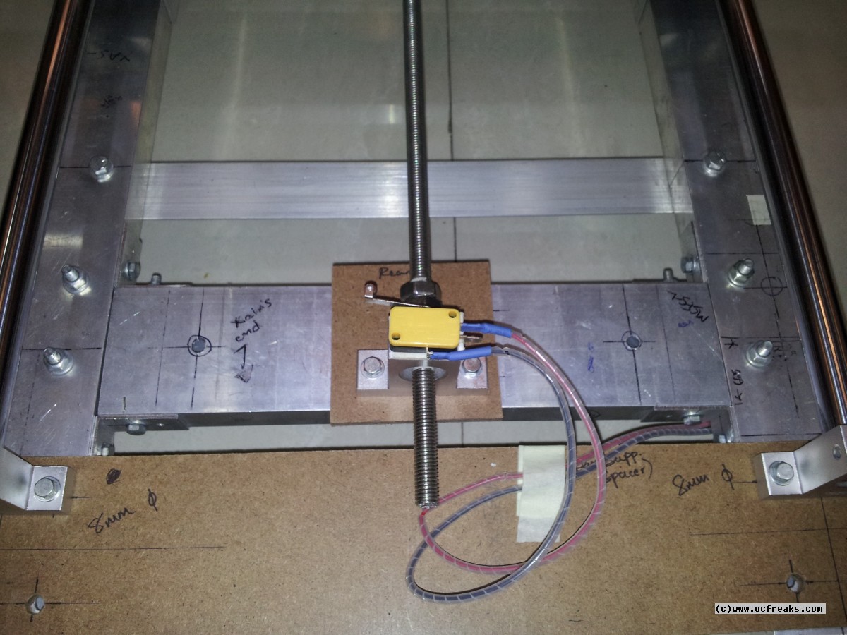
X-axis Limit/Home Switches:
Z-axis Limit/Home Switches:
CNC Base assembly:
The Gantry:
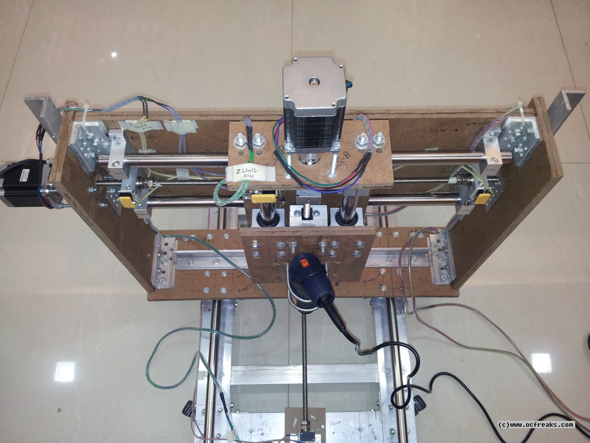
CNC almost complete! :
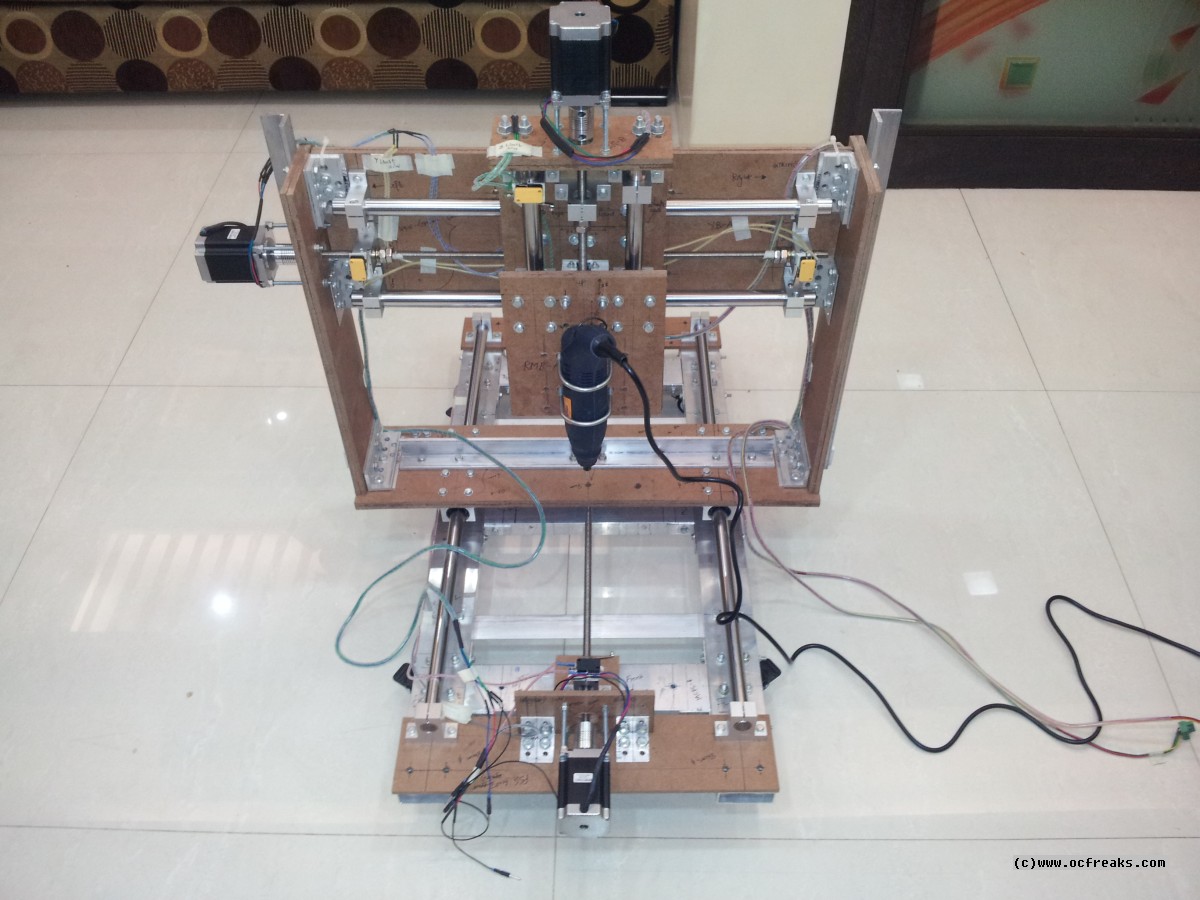
CNC on Wheels! :
The final setup for Test Runs:
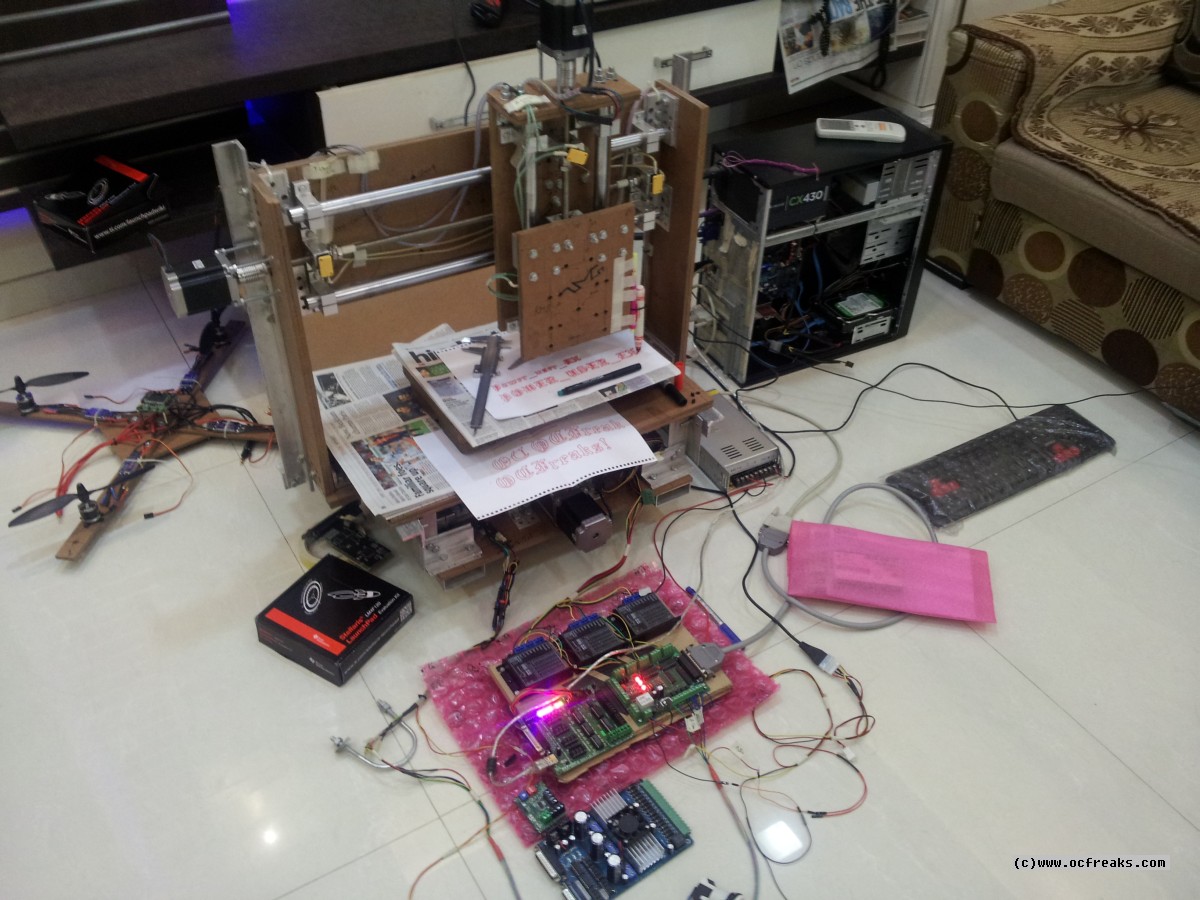
Test Print(after calibration) Result:
And its Made in India. (: