In this tutorial we will see how to interface an IR(Infra-Red) photo-diode with ARM7 LPC2148 microcontroller. A photodiode is a diode but additionally also converts light i.e. incident photons into electrical current. An IR photodiode is a photodiode which is sensitive to IR light. These photodiodes are easily identifiable since they are black. An IR diode pair i.e. an IR Photodiode along with an IR LED can be used to sense obstacle or as proximity sensor. It is also used in line-follower robots.
Working principle
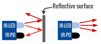
IR LED is used as a source of Infra-Red light (Transmitter). A revered-biased IR photodiode (Sensor,Receiver) is used to detect any IR light reflected from objects in front of the pair. When reflected IR light falls on the IR photodiode it generates a small amount of current corresponding to amount of incident light and in this way it acts as an IR sensor. We can then convert this current into voltage to interface with a micrcontroller using ADC. The analog output can also be converted into 1-bit digital output using a comparator. Commonly available IR modules include a comparator(Op-AMP) or a schmitt-trigger and provide 1-bit digital output (HIGH/LOW) to indicate whether an obstacle is present or not. This makes it easy to interface IR diode pair without using ADC.

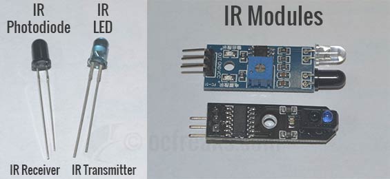
IR Photodiode/LED pair (Rx/Tx) and Modules:

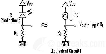
Converting Photo Diode current to Voltage
We can convert the IR photodiode(IR Sensor) current into proportional voltage by using a Load Resistance RL. The reverse bias photodiode current (IPD) flowing through the Load Resistance creates a voltage drop which we can measure. Note that the photodiode is reverse biased and a bias voltage is given. This configuration is also known as photoconductive mode. The configuration where bias voltage is absent is called Photovoltaic mode.

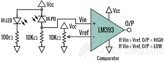
We can also use an Op-AMP/Comparator to convert analog signal into digital signal using a potentiometer to set a threshold voltage which defines the sensing or triggering distance. In the diagram given below, the voltage drop is fed into non-inverting pin of LM393 Comparator as Vin. The middle leg of a 10K potentiometer is connected to inverting pin of LM393 Comparator as Vref which sets the thresholds. Depending on Vin and Vref, the comparator output is either HIGH i.e. Logic 1 or LOW i.e. Logic 0. The condition when the output is either 1 or 0 is given in the diagram. For the circuit given below a HIGH means an obstacle is detected and a LOW means no obstacle is detected. Instead of LM393 you can use any general purpose Op-AMP like LM358/LM324 as a comparator.

Similar kind of circuit is present on IR modules used for proximity sensing, obstacle detection, etc. The potentiometer on these modules is used to set the sensing range/distance. Some IR modules used for line-following robots incorporate a schmitt trigger i.e IC 7414 to convert output to digital(HIGH/LOW). The hysteresis curve of schmitt trigger defines a fixed sensing range/distance in these modules.
IR Interfacing Examples with ARM7 LPC2148
Interfacing IR photodiode using LPC214x ADC
In this example we will convert the reverse bias current of IR photodiode into proportional voltage using a 10K resistor in presence of 3.3V(Vcc) biasing voltage. We will use the inbuilt ADC of LPC2148 to convert the voltage into digital readings. You can check my ADC Tutorial for more. We can set a threshold for the digital values to define sensing range. The ADC readings are inversely proportional to the proximity of an object in front. The code is very similar to LDR Interfacing tutorial. The example project linked below also contains retargeted printf() for KEIL which redirects its output to UART0.
Schematic:


Example 1 Source Code:
/*(C) Umang Gajera- www.ocfreaks.com
LPC2148 IR Sensor Interfacing Example 1 Source Code for KEIL ARM.
More Embedded tutorials @ www.ocfreaks.com/cat/embedded/
Also see: https://www.ocfreaks.com/lpc2148-adc-programming-tutorial/
License: GPL.*/

#include <lpc214x.h>
#include <stdio.h> //visit https://www.ocfreaks.com/retarget-redirect-printf-scanf-uart-keil/
#include "lib_funcs.h" //OCFreaks LPC214x Tutorials Library Header

#define AD06 ((1<<9)|(1<<8)) //Select AD0.6 function for P0.4
#define SEL_AD06 (1<<6)
#define CLKDIV (15-1) // 4Mhz ADC clock (ADC_CLOCK=PCLK/CLKDIV) where "CLKDIV-1" is actually used , in our case PCLK=60mhz
#define BURST_MODE_OFF (0<<16) // 1 for on and 0 for off
#define PowerUP (1<<21)
#define START_NOW ((0<<26)|(0<<25)|(1<<24)) //001 for starting the conversion immediately
#define ADC_DONE (1UL<<31)

#define VREF 3.3 //Reference Voltage at VREF pin

int main(void)
{
	initClocks(); //Set PCLK = CCLK = 60Mhz - used by: UART, Timer and ADC
	initUART0(); //Initialize UART0 for retargeted printf()
	initTimer0(); //Init Timer for delay functions

	PINSEL0 |= AD06 ; //select AD0.6 for P0.4
	int result = 0;
	unsigned long AD0CR_setup = (CLKDIV<<8) | BURST_MODE_OFF | PowerUP; //Setup ADC block

	printf("OCFreaks.com LPC214x IR Sensor Interfacing Tutorial - Example 1.\n");

	while(1)
	{
		AD0CR =  AD0CR_setup | SEL_AD06;
		AD0CR |= START_NOW; //Start new Conversion

		while( (AD0DR6 & ADC_DONE) == 0 );

		result = (AD0DR6>>6) & 0x3FF; //get the 10bit ADC result

		printf("AD0.6 = %d\n" , result); //Print raw ADC values corresponding to IR photo-diode reverse current
		delayMS(500); //Slowing down Updates to 2 Updates per second
	}

	//return 0; //This won't execute normally
}
Interfacing IR Proximity-Sensor/Obstacle-avoidance Module with ARM7 LPC2148 using GPIO
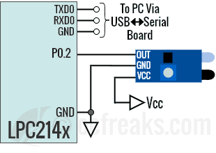
In this example will interface the IR module using Pin P0.2. Check the output logic of your IR module and edit the code accordingly. For commonly available IR Proximity Sensor modules, a LOW output means an Obstacle is detected else output is HIGH. For line-follower IR modules based on Schimtt-trigger, a HIGH output means an Obstacle is detected else output is LOW.
Schematic:

Example 2 Source Code:
/*(C) Umang Gajera- www.ocfreaks.com
LPC2148 IR Proximity/Obstacle-avoidance Sensor Interfacing Example 2 Source Code for KEIL ARM.
More Embedded tutorials @ www.ocfreaks.com/cat/embedded/
License: GPL.*/

#include <lpc214x.h>
#include <stdio.h> //visit https://www.ocfreaks.com/retarget-redirect-printf-scanf-uart-keil/
#include "lib_funcs.h" //OCFreaks LPC214x Tutorials Library Header
#define PIN0_2 (1<<2)

int main(void)
{
	initClocks(); //Set PCLK = CCLK = 60Mhz - used by: UART, Timer
	initUART0(); //Initialize UART0 for retargeted printf()
	initTimer0(); //Init Timer for delay functions

	printf("OCFreaks.com LPC214x IR Sensor Interfacing Tutorial - Example 2.\n");

	while(1)
	{
		//Check the O/P Logic of your IR module. Mine gives LOW when obstacle is detected else HIGH.
		if((IO0PIN & PIN0_2) == 0 )
		{
			printf("Obstacle Detected!\n");
		}
		else
		{
			printf("No Obstacle ahead.\n");
		}

		delayMS(500); //Slowing down Updates to 2 Updates per second
	}

	//return 0; //This won't execute normally
}