In this tutorial I will discuss, how to interface an Ultrasonic distance sensor (HC-SR04) with ARM Cortex-M3 LPC1768 microcontroller. The HC-SR04 Ultrasonic Distance/Ranging Sensor uses ultrasound to measure distance from a object ahead of the sensor. Ultrasound is a soundwave having frequency greater than the audible limit i.e. > 20Khz. HCSR-04 module uses 40Khz ultrasound to measure distance between itself and any object ahead of it with a sensing range of 2 centimeters to 4 meters.
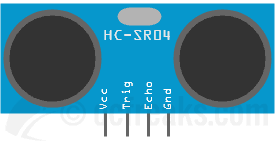
Pinout: The module has got 4 pins viz. VCC(+5V), TRIG, ECHO, GND.

Working principle
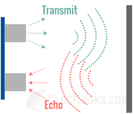
Ultrasonic Distance/Ranging Sensors are based on similar working principle to what is used in SONAR. It has got two transducers, one for transmitting ultrasound and second one for receiving the echo. Based on the time it takes for the echo to arrive we can compute the distance, since we already know the speed of sound in air which is around 343 m/s or 1235 km/h (at 20°C).

HC-SR04 Interfacing Steps:
- To start distance measurement a short pulse of 10us is applied to Trigger pin.
- After receiving trigger pulse, the HC-SR04 Module sends a burst of 8 ultrasonic pulses at 40Khz.
- It will then output a HIGH for the amount to time taken for the sound waves to reach back.
- The pulse HIGH time is measured and then used to calculate the distance.

Distance calculations:
We know speed of sound in air,
We also know the time it took for sound waves to emit and echo back, lets call this time taken T. Now, by using basic distance formula we can find the distance as:
Now, since we will be measuring ECHO ON-Time in microseconds and also to get distance in centimeters we can change the units as follows:
After this we divide the computed value by 2 since the waves have traveled double distance.
=
cm
HC-SR04 Ultrasonic sensor Interfacing with LPC1768 Example
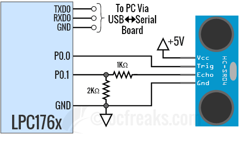
In the interfacing example given below, P0.0 of LPC176x is configured as output and connected to TRIG pin and P0.1 is configured as input and connected to ECHO pin of the Ultrasonic Distance sensor. Timer0 module is used for generating delays with 1 us resolution. It is also used to measure time for ECHO pulse using two simple functions viz. startTimer0() & stopTimer0(). You can check the project source code linked below for implementation details. The distance data is sent to Terminal via UART0. You can refer my LPC1768 UART Tutorial for more. The example source code also contains retargeted printf() for KEIL which redirects its output to UART0.
Schematic:

Source Code:
/*(C) Umang Gajera - www.ocfreaks.com
Interfacing HC-SR04 Ultrasonic Distance/Ranging sensor with LPC1768/LPC1769 - Example Source Code for KEIL ARM.
More Embedded tutorials @ www.ocfreaks.com/cat/embedded/
License: GPL.*/

#include <lpc17xx.h>
#include <stdio.h> //for printf() - https://www.ocfreaks.com/retarget-redirect-printf-scanf-uart-keil/
#include "ocf_lpc176x_lib.h" //contains initUART0(), initTimer0() & putc() to retarget printf()

#define TRIG (1<<0) //P0.0
#define ECHO (1<<1) //P0.1

int main(void)
{
	//SystemInit(); //Gets called by Startup code, sets CCLK=100Mhz, PCLK=25Mhz
	initUART0(); //Initialize UART0 for retargeted printf() - defined in ocf_lpc176x_lib.c
	initTimer0(); //Init Timer for delay functions - defined in ocf_lpc176x_lib.c
	int echoTime=0;
	float distance=0;

	LPC_GPIO0->FIODIR |= TRIG;    //Set P0.2(TRIG) as output
	LPC_GPIO0->FIODIR &= ~(ECHO); //Set P0.3(ECHO) as input (explicitly)
	LPC_GPIO0->FIOCLR |= TRIG;    //Set P0.2 LOW initially

	printf("OCFreaks.com LPC176x HC-SR04 Sensor Interfacing Tutorial\n");

	while(1)
	{
		//Output 10us HIGH on TRIG pin
		LPC_GPIO0->FIOPIN |= TRIG;
		delayUS(10);
		LPC_GPIO0->FIOCLR |= TRIG;

		while(!(LPC_GPIO0->FIOPIN & ECHO)); //Wait for a HIGH on ECHO pin
		startTimer0(); //Start counting
		while(LPC_GPIO0->FIOPIN & ECHO); //Wait for a LOW on ECHO pin
		echoTime = stopTimer0(); //Stop counting and save value(us) in echoTime

		distance = (0.0343 * echoTime)/2; //Find the distance

		printf("Distance = %0.2fcm\n",distance);

		delayMS(1000); //1 update per second
	}
	//return 0; //This won't execute normally
}
Download Project:
Screenshot:

