This time we will go through a tutorial on Interfacing LDR with ARM7 LPC2148 microcontroller. Light Dependent Resistor (i.e. LDR for short) is basically used to detect the intensity of light and hence, for example, we can detect if a room is dark or lit. They are also known as photoresistors or photoconductive cells. The resistance of LDR is inversely proportional to the intensity of light. Hence under dark conditions the resistance typically rises to around 500K to 5M. Under ambient light the resistance is generally around 2K to 10K. Under very bright light its resistance falls down to around few ohms, for example around 2 to 20 ohms.
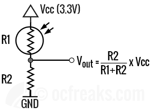
For the examples covered in this tutorial, we will use the on-chip ADC module of LPC214x microcontroller to interface LDR. You can check my LPC2148 ADC Programming Tutorial for reference. Since we cannot directly connect an LDR to the ADC’s input, we need to convert the resistance into an equivalent voltage. Once we do this it becomes very easy to interface them. By adding another fixed resistor in series we can form a potential divider network and can connect the common of the resister and LDR to ADC’s input pin. Lets call LDR as R1 and the fixed resistor as R2. The voltage Vout at the common terminal is given as:

Now, to implement this we need a suitable value for R2. The value of R2 in voltage-divider is primarily determined by:
- LDR’s maximum current
- LDR’s Response curve [Resistance Vs LUX] (which factors in resistance in dark, bright light and ambient light)
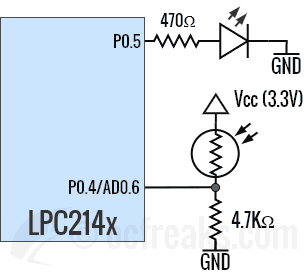
Most of the time using 3.3K or 4.7K or 10K resistor as R2 will do the job. But, always check the manufacturer’s datasheet for max operating current. In case you don’t have access to datasheet, then generally a couple of few milliamps must be safe to operate. For the ones which I have used (which have come in ~5mm package), generally 1mA to 5mA have not been an issue. Some LDR’s also allow 50mA to 75mA+ max current. In my case a resistor of 4.7K just works fine and gives a good full scale range. Given LPC2148 uses 3.3V as Vcc, a resistor of 4.7K will limit current to 0.7mA max through LDR under very bright conditions.
Example 1 – Reading the voltage divider output:
In this example we will read the voltage divider output, which changes as the intensity of light changes. The ADC will convert the input voltage to a proportional value between 0 and 1023. We can directly use this value(ADC Result) to detect the light intensity. A value of 0 means Dark condition and a value of 1023 means very bright light is present. With this example you can see the output values change as you change the intensity of light. Working with this example you can decide on a cut-off value or a cut-off range to trigger a function. In this example I have retargeted printf() to redirect its output over UART. Here is the schematic for interfacing LDR with ARM7 LPC2148:


Source code:
/*(C) Umang Gajera- www.ocfreaks.com
More Embedded tutorials @ www.ocfreaks.com/cat/embedded/
LPC2148 LDR Interfacing Example 1 Source Code for KEIL ARM.
Also see: https://www.ocfreaks.com/lpc2148-adc-programming-tutorial/
License: GPL.*/

#include <lpc214x.h>
#include <stdio.h> //For retargeted printf()
#include "lib_funcs.h" //OCFreaks LPC214x Tutorial Library Header

#define AD06 ((1<<9)|(1<<8)) //Select AD0.6 function for P0.4
#define SEL_AD06 (1<<6)
#define CLKDIV (15-1) // 4Mhz ADC clock (ADC_CLOCK=PCLK/CLKDIV) where "CLKDIV-1" is actually used , in our case PCLK=60mhz
#define BURST_MODE_OFF (0<<16) // 1 for on and 0 for off
#define PowerUP (1<<21)
#define START_NOW ((0<<26)|(0<<25)|(1<<24)) //001 for starting the conversion immediately
#define ADC_DONE (1UL<<31)

#define VREF 3.3 //Reference Voltage at VREF pin

int main(void)
{
	initClocks(); //Set PCLK = CCLK = 60Mhz - used by: UART, Timer and ADC
	initUART0(); //Initialize UART0 for retargeted printf()
	initTimer0(); //Init Timer for delay functions

	PINSEL0 |= AD06 ; //select AD0.6 for P0.4
	int result = 0;
	unsigned long AD0CR_setup = (CLKDIV<<8) | BURST_MODE_OFF | PowerUP; //Setup ADC block

	printf("OCFreaks.com LPC214x LDR Interfacing Tutorial - Example 1.\n");

	while(1)
	{
		AD0CR =  AD0CR_setup | SEL_AD06;
		AD0CR |= START_NOW; //Start new Conversion

		while( (AD0DR6 & ADC_DONE) == 0 );

		result = (AD0DR6>>6) & 0x3FF; //get the 10bit ADC result

		printf("AD0.6 = %d\n" , result);
		delayMS(500); //Slowing down Updates to 2 Updates per second
	}

	//return 0; //This won't execute normally
}
Example 2 – Turn on LED when its dark:
This is a classic example for LDRs. Here we will turn-on an LED when we detect low light or dark conditions. Instead of an LED you can also connect a Relay which can then switch on a Bulb or something like heater during night in cold regions. Make sure you keep the LDR away from the LED or Bulb since we are only interested in detecting sunlight and not artificial light in this case. Schematic for this example is given as follows:

Source code:
/*(C) Umang Gajera- www.ocfreaks.com
More Embedded tutorials @ www.ocfreaks.com/cat/embedded/
LPC2148 LDR Interfacing Example 2 Source Code for KEIL ARM.
Also see: https://www.ocfreaks.com/lpc2148-adc-programming-tutorial/
License: GPL.*/

#include <lpc214x.h>
#include "lib_funcs.h" //OCFreaks LPC214x Tutorial Library Header

#define AD06 ((1<<9)|(1<<8)) //Select AD0.6 function for P0.4
#define SEL_AD06 (1<<6)
#define CLKDIV (15-1) // 4Mhz ADC clock (ADC_CLOCK=PCLK/CLKDIV) where "CLKDIV-1" is actually used , in our case PCLK=60mhz
#define BURST_MODE_OFF (0<<16) // 1 for on and 0 for off
#define PowerUP (1<<21)
#define START_NOW ((0<<26)|(0<<25)|(1<<24)) //001 for starting the conversion immediately
#define ADC_DONE (1UL<<31)
#define VREF 3.3 //Reference Voltage at VREF pin

#define CUT_OFF 200 //Define your cut-off value here

int main(void)
{
	initClocks(); //Set PCLK = CCLK = 60Mhz
	initTimer0(); //Init Timer for delay functions

	PINSEL0 |= AD06 ; //select AD0.6 for P0.4
	IO0DIR |= (1<<5); //Select P0.5 as output
	int result = 0;
	unsigned long AD0CR_setup = (CLKDIV<<8) | BURST_MODE_OFF | PowerUP; //Setup ADC block

	while(1)
	{
		AD0CR =  AD0CR_setup | SEL_AD06;
		AD0CR |= START_NOW; //Start new Conversion

		while( (AD0DR6 & ADC_DONE) == 0 );

		result = (AD0DR6>>6) & 0x3FF; //get the 10bit ADC result

		if(result < CUT_OFF)
		{
			IO0SET = (1<<5); //LED ON
		}
		else
		{
			IO0CLR = (1<<5); //LED OFF
		}

		delayMS(100); //wait some time since LDRs don't react immediately.
	}
	//return 0; //This won't execute normally
}