Microcontrollers based on ARM Cortex-M processor feature Nested Vectored Interrupt Controller or NVIC for handling interrupts. NVIC in ARM Cortex-M3 (ARMv7-M) implements fixed 8-bit priority fields in Interrupt Priority Register (IPR), thereby giving us up to 256(28) priority levels. But, not all of the ARM Microcontrollers implement 8 bits for priority levels, in which case the remaining priority bits are treated as Zeros because the field size is fixed to 8 bits. The un-implemented bits are LSb aligned. Generally the implemented bits are in proportion with number of external(peripheral) interrupts a given microcontroller supports. These priority fields are stored in the Interrupt Priority Register. Each priority register is 32-bits wide and holds 4 priority fields. This is as shown below:


Here, IRPn represents nth Interrupt Priority Register. PRI_m is the Priority field for Interrupt m (IRQm).
- The IPR number n for Interrupt m is the Quotient of “m/4” i.e. n = (int)m/4 = m DIV 4
- The byte offset is the remainder of “m/4” i.e. offset = m % 4 = m MOD 4
In Cortex-M3, each of these fields can be further sub-divided into two parts, which are:
- Preemption Priority or Group Priority level: This is upper part(sub-field) of the 8-bit priority field. This is the main priority level which defines the preemption of interrupt exceptions or IRQs. An Interrupt will preempt the execution of the current Interrupt, if its Group Priority is higher than the Interrupt being currently serviced. Lower priority values denote higher priority & vice-versa.
- Sub-Priority Level: This comes into picture when there are multiple pending interrupts having same preemption or Group Priority. In this case the sub-priority will determine which Interrupt gets executed first. Also note that, if pending ISRs have same Group and Sub-Group priority then the Interrupt having the lowest IRQ number will be executed first.
Cortex-M0 Processor only implements 2 bits in the priority field [7:6] and rest bits [5:0] are always treated as Zeros, thereby supporting only 4 unique priority levels. This implementation is fixed for all MCUs which use Cortex-M0 (ARMv6-M) CPU. It also doesn’t implement Interrupt Priority Grouping.
Interrupt Priority Groups in ARM Cortex-M3
Based on the sub-divisions, priority groups are formed depending on how many bits are used for preemption and sub-priority levels. The master table which assigns a Priority Grouping Number for each of the 8 possible divisions is shown below:
| Priority Grouping Number | Split Point | Group Priority Bits (x) | Sub Priority Bits (y) | Total Group Priorities | Total Sub Priorities |
|---|---|---|---|---|---|
| 0 | [xxxxxxx.y] | [7:1] | [0] | 128 | 2 |
| 1 | [xxxxxx.yy] | [7:2] | [1:0] | 64 | 4 |
| 2 | [xxxxx.yyy] | [7:3] | [2:0] | 32 | 8 |
| 3 | [xxxx.yyyy] | [7:4] | [3:0] | 16 | 16 |
| 4 | [xxx.yyyyy] | [7:5] | [4:0] | 8 | 32 |
| 5 | [xx.yyyyyy] | [7:6] | [5:0] | 4 | 64 |
| 6 | [x.yyyyyyy] | [7] | [6:0] | 2 | 128 |
| 7 | [.yyyyyyyy] | N/A | [7:0] | 1 | 256 |
This Priority Grouping is common for all ARM Cortex-M3 processor based microcontrollers. Any of the 8 possible grouping can be selected using the PRIGROUP field (bits[10:8]) of the AIRCR (Application Interrupt and Reset Control Register). The Priority Grouping Number value shown in the table is assigned to the PRIGROUP field of AIRCR.
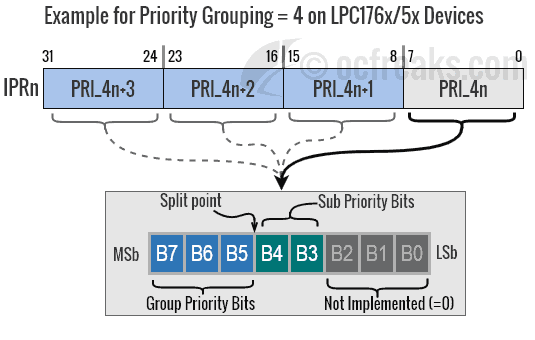
For MCUs which implement less than 8 bits, the non-implemented bits are treated as Zeros in the table above. For example LPC17xx devices (like LPC1768/LPC1769) implement only 5 bits for Priority. The remaining(lower) 3 bits are treated as Zeros. This is shown below:
LPC176x Interrupt Priority Grouping
| Priority Grouping Number | Split Point | Group Priority Bits (x) | Sub Priority Bits (y) | Total Group Priorities | Total SubGroup Priorities |
|---|---|---|---|---|---|
| 0,1,2 | [xxxxx.000] | [7:3] | N/A | 32 | 1 |
| 3 | [xxxx.y000] | [7:4] | [3] | 16 | 2 |
| 4 | [xxx.yy000] | [7:5] | [4:3] | 8 | 4 |
| 5 | [xx.yyy000] | [7:6] | [5:3] | 4 | 8 |
| 6 | [x.yyyy000] | [7] | [6:3] | 2 | 16 |
| 7 | [.yyyyy000] | N/A | [7:3] | 1 | 32 |
An Example with Priority Grouping of 5 on LPC17xx Devices which implement 5 bits for Priority is as follows:

STM32 (STM32F10xxx) Interrupt Priority Grouping
Priority Grouping for other Cortex-M3 MCUs from the STM32 family like STM32F103, etc.. which implement only 4 bits of interrupt priority is given below.
| Priority Grouping Number | Split Point | Group Priority Bits (x) | Sub Priority Bits (y) | Total Group Priorities | Total SubGroup Priorities |
|---|---|---|---|---|---|
| 0,1,2,3 | [xxxx.0000] | [7:4] | N/A | 16 | 1 |
| 4 | [xxx.y0000] | [7:5] | [4] | 8 | 2 |
| 5 | [xx.yy0000] | [7:6] | [5:4] | 4 | 4 |
| 6 | [x.yyy0000] | [7] | [6:4] | 2 | 8 |
| 7 | [.yyyy0000] | N/A | [7:4] | N/A | 16 |
Similarly we can get the Priority Grouping table for LPC13xx devices like LPC1343/LPC1347 using the master table. Note that LPC134x MCUs implement only 3 bits of Priority hence can give 8 unique priority levels.
PRIGROUP can get a bit confusing since the unimplemented bits are towards the LSb i.e. in the lower half starting from bit location 0. But thankfully all of this hassle is handled by the CMSIS library.
Assigning/Programming Priority Levels using CMSIS
The CMSIS NVIC functions defined in core_cm3.h header defines standard interfaces for Configuring and Assigning Interrupt Priority levels which are listed below. These functions take care of aligning the priority bits as required, if the number of implemented bits are less than 8. First lets see the declarations of these functions.
void NVIC_SetPriorityGrouping(uint32_t PriorityGroup);

uint32_t NVIC_GetPriorityGrouping(void);

uint32_t NVIC_EncodePriority(uint32_t PriorityGroup, uint32_t PreemptPriority, uint32_t SubPriority);

void NVIC_DecodePriority(uint32_t Priority, uint32_t PriorityGroup, uint32_t* pPreemptPriority, uint32_t* pSubPriority);

void NVIC_SetPriority(IRQn_Type IRQn, uint32_t priority);

uint32_t NVIC_GetPriority(IRQn_Type IRQn);
- NVIC_SetPriorityGrouping(): This function is used to select the Priority Grouping. The parameter PriorityGroup is the Priority Grouping Number as given the Tables above. This function changes the PRIGROUP bits[10:8] of AIRCR(Application Interrupt & Reset Control Register) register which defines how the Priority Fields in IPRs are split.
- NVIC_GetPriorityGrouping(): It returns the Priority Grouping(0 to 7) currently selected.
- NVIC_EncodePriority(..): This function will return “encoded” Priority Field for given a Priority Grouping(0 to 7), Preempt Priority and Sub-Priority. This function automatically takes care of un-implemented bits. The value returned by this function can be directly assigned to required Priority field in IPRn using NVIC_SetPriority(..).
- NVIC_DecodePriority(..): This function will “decode” the Priority Field into Pre-empt Priority and Sub-Priority for a given Priority Grouping(0 to 7).
- NVIC_SetPriority(..): As the name suggestes, it is used to assign a priority for given Interrupt source. Note that the parameter priority must be in accordance with Priority Grouping selected, hence NVIC_EncodePriority() must be used to encode priority before calling this function.
- NVIC_GetPriority(..): Returns the priority value for given IRQ.
C/C++ Example 1:
#include <lpc17xx.h>

int main(void)
{
	unsigned int priority = 0;

	NVIC_SetPriorityGrouping(4);
	/* bits[7:5] used for Group Priority
	   bits[4:3] used for Sub-Group Priority */

	priority = NVIC_EncodePriority(4,2,0);
	/*4= Priority Grouping, 2= Group Priority, 0= Sub-Priority*/

	NVIC_SetPriority(TIMER0_IRQn,priority); //Set new Priority

	while(1)
	{
		/*Code.*/
	}

	//return 0;
}
C/C++ Example 2:
#include <lpc17xx.h>
#define NUM_IRQn 35 //Total number of peripheral interrupts
#define PRIGROUP_4 4
#define DEFAULT_GROUP_PRI 7
#define DEFAULT_SUB_PRI 3
#define TIMER2_GROUP_PRI 2
#define TIMER2_SUB_PRI 0

int main(void)
{
	unsigned int priority = 0, priGroup = 0;

	NVIC_SetPriorityGrouping(PRIGROUP_4);
	/* bits[7:5] used for Group Priority
	   bits[4:3] used for Sub-Group Priority */

	priGroup = NVIC_GetPriorityGrouping();

	priority = NVIC_EncodePriority(priGroup, //=4
							DEFAULT_GROUP_PRI, //=7, Preempt/Group Priority
							DEFAULT_SUB_PRI); //=3, SubPriority within Group

	for(int currIRQ = 0; currIRQ < NUM_IRQn; currIRQ++ )
	{
		NVIC_SetPriority(currIRQ, priority); //Set new default Priorities for all peripheral IRQs
	}

	priority = NVIC_EncodePriority(priGroup, //=4
							TIMER2_GROUP_PRI, //=2, Preempt/Group Priority
							TIMER2_SUB_PRI); //=0, SubPriority within Group

	NVIC_SetPriority(TIMER2_IRQn, priority); //Set new higher priority for TIMER2 IRQ

	while(1)
	{
		/*Code.*/
	}

	//return 0;
}
Exception Mask Registers
ARM Cortex-M3 implements three Exception Mask Registers which are used to disable the execution of certain group or type of Interrupts/Exceptions where they can impact the performance of time critical tasks. This is more useful for applications having real time constraints, where the system has to gurantee completion of certain tasks within required time-frame. These registers can be only accessed via core register access functions provided by CMSIS which are defined in core_cmFunc.h.
PRIMASK - Priority Mask Register
PRIMASK register is used to disable interrupts which have configurable priority i.e. External/Peripheral Interrupts when bit[0] in this register is set to 1. When set to 0 this register won't have any effect on interrupts. Rest of the bits[31:1] are reserved.
CMSIS provides 2 functions to access this register viz:
- void __set_PRIMASK(uint32_t priMask)
- uint32_t __get_PRIMASK(void)
FAULTMASK - FAULT Mask Register
FAULTMASK register is used to disable all interrupts execpt Non-Maskable Interrupt(NMI) when bit[0] in this register is set to 1. When set to 0 this register won't have any effect on interrupts. Rest of the bits[31:1] are reserved.
CMSIS provides 2 functions to access FAULTMASK register viz:
- void __set_FAULTMASK(uint32_t faultMask)
- uint32_t __get_FAULTMASK(void)
BASEPRI - Base Priority Mask Register
BASEPRI register defines the minimum priority to service interrupts. Only Bits[7:0] are used. This 8-bit field is same as the priority field in IPRs. When a certain non-zero 8-bit priority value is set to this register, then it will disable all interrupts having same or lower priority than the value set. If this register is set to 0 then it won't have any effect. Note that this function doesn't shift the priority bits in case some bits are not implemented. The user is responsible for left shifiting the bits by (8 - __NVIC_PRIO_BITS) where __NVIC_PRIO_BITS is number of implemented priority bits which is defined in the device header file.
CMSIS provides 2 functions to access BASEPRI register viz:
- void __set_BASEPRI(uint32_t basePri)
- uint32_t __get_BASEPRI(void)