This time I will discuss ARM Cortex-M0 LPC1114 Pulse Width Modulation (PWM) Tutorial. This programming guide is also applicable for other devices of same family like LPC1115. I will also cover 2 simple LPC1114 PWM examples. I assume you are comfortable with Timers in ARM Cortex-M0 based LPC11xx micro-controllers since PWM block is basically a Timer with PWM mode enabled. Please go through the previous tutorial since we will be using the same registers except for PWM Control Register which is covered in this tutorial.
Pulse Width Modulation (PWM) Basics:
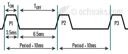
I’ve have posted a Beginner PWM tutorial. If you are new to PWM please have a look there. A Diagram that sums it up is given below. It shows Single Edge Non-Inverting or Left-Aligned PWM with TON, TOFF & Period. Duty Cycle is simply TON Divided by Period.

ARM Cortex-M0 LPC1114 PWM Module
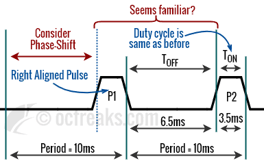
In LPC11xx Microcontrollers a dedicated PWM block is absent. Instead, PWM support is integrated in the Timers themselves. We just need to use them in PWM mode to generate PWM. LPC111x micro-controllers only support Single Edge PWM outputs. More over, the way PWM support is implemented in these microcontrollers, the PWM pulse is Leading-Edge or Right-Aligned compared to Trailing-Edge or Left-Aligned PWM which is more common. But thankfully, this does not change the way we control external PWM controlled devices since Leading-Edge/Right-Aligned PWM is just a Phase-Shifted Left-Aligned pulse – with the only condition that Duty Cycle (hence TON) remains the same. Given this condition is satisfied: consider it having a “offset” at the beginning, afterwhich its basically Left-Aligned PWM if you disregard the “initial-offset” or phase-shift. Here is what it looks like:

Since we are using Timer in PWM mode, calculations for Prescale and configuration is exactly the same. Essentially we have two 16-bit PWM blocks and two 32-bit PWM blocks. Each capable of generating 3 PWM outputs using first 3 match registers (MR0 to MR2). The last match register (MR3) is used to set the PWM Period. The Match outputs pins are used get the PWM output when PWM mode is enabled for the corresponding Match output. Please refer my previous timer tutorial for MAT pins.
- All PWM outputs will go LOW at the beginning of a PWM cycle unless their match value is 0.
- Each PWM output will go HIGH when its match value is reached. Note: If no match occurs i.e Match value is greater than Period then the output will remain LOW!
- If the Match value is greater than PWM Period or the Cycle Time, and PWM signal is already HIGH, then the signal will be made LOW at the start of next cycle.
- If Match value is same as the Period, then PWM output will be reset to LOW at the next clock tick after TC reaches its reset value. Hence, we end up getting one clock pulse at the beginning. This implies we can never get 0% duty-cycle. Its almost 0% but not 0%!
- If Match value is zero then PWM output will be HIGH continuously.
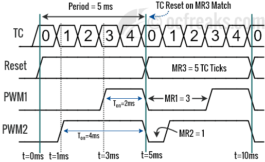
Consider that our PWM Period duration is 5 milliseconds and TC increments every 1 millisecond using appropriate prescale value. We set MR3 to 5 i.e. 5 ticks of PWM TC. We have MR1 = 2 and MR2 = 4. We using TOFF as Match values. Whenever the value in TC matches the value in any of the match register, its corresponding output it set to HIGH until the start of next PWM cycle as shown in PWM Timing Diagram below:

Registers used in LPC1114 PWM Programming
I have already explained TCR, PR, MRx & MCR registers in previous LPC1114 Tutorial, so I won’t explaining them in detail except for PWMC.
2) PR – (PWM) Prescale Register: Used to control the resolution of the PWM outputs. The Timer Counter(TC) will increment every PR+1 Peripheral Clock Cycles (PCLK).
3) MR0 – MR3 (Match Registers): These four Match registers contain Pulse TOFF (or LOW Time) Values i.e the Number of TC Ticks required to change the output from LOW to HIGH..
4) MCR – (PWM) Match Control Registers: It is used to specify what operations can be done when the value in a particular Match register equals the value in TC – Either generate an Interrupt, or Reset the TC, or Stop, which stops the counters.
5) PWMC (TM32BxPWMC) – PWM Control Register: It is used to configure Match outputs as PWM outputs. As mentioned earlier only three PWM outputs can be used at a time since one additional Match Register is used to generate the PWM Period. As recommended by the User Manual MR3 must be used to generate the Period. Only the first 4 bits are used, one for each Match Output. BITx is used to enable PWM Mode for MATx. Hence BIT0 for MAT0, BIT1 for MAT1 and so on. When a bit is 0 the corresponding Match Output is defined by EMx Bit in EMR register. When a bit is 1, PWM Output is enabled for the corresponding Match Output Pin. We are only interested in setting these bits to 1.
Configuring and Initializing PWM in LPC111x
Now lets see how to configure PWM. First we need to do some basic Calculations for defining the PWM Period time and the PWM Resolution using a prescale value. For this first we need to define the resolution of our PWM signal. PWM resolution is the minimum time delay that can used to increase or decrease the pulse width. More smaller the increment more fine will be the resolution. PWM Resolution is set using an appropriate Prescale Value.
LPC1114 PWM Prescale Calculations:
The general formula for PWM Resolution at X Mhz PCLK(CCLK) and a given value for prescale (PR) is as given below:
=
Seconds
Hence, we get the Formula for Prescaler (PR) for required PWM resolution (PWMRES in Secs) at given PCLK(in Hz) frequency as:
Note that here, the PWM Resolution is also the time delay required to increment TC by 1.
Hence, Prescaler value for 1 micro-second resolution i.e. 1us time delay at 48 Mhz PCLK(CCLK) is,
Note: with “PCLK” I basically mean CCLK since for LPC11xx Microcontrollers: PCLK=CCLK.
- Select the MATx function for the PIN on which you need the PWM output using applicable LPC_IOCON register.
- Assign the Calculated value to PR.
- Set the Value for PWM Period in MR3.
- Set the Values for other Match Registers i.e the Pulse Widths.
- Set appropriate bit values in MCR For e.g. Reset on MR3 Match for using MR3 to define PWM Period
- Then Enable PWM outputs using PWMC.
- Now Reset PWM Timer using TCR.
- Finally, Enable TC using TCR.
Example :
//Select MATn.x Function Using appropriate IOCON register for PWM output
LPC_IOCON->..    = ... ; //Select MATx Function for pins being used
LPC_TMRnBx->PR   = ... ; //assign calculated PR value
LPC_TMRnBx->MR3  = ... ; //Assign PWM Period Duration
LPC_TMRnBx->MRx  = ... ; //Assign Pulse off duration i.e. TOFF for other Match Regs
LPC_TMRnBx->MCR  = (1<<10); //Reset TC on MR3 match
LPC_TMRnBx->PWMC = ... ; //enable PWM mode for MATx pins as required
LPC_TMRnBx->TCR  = 0x2; //Reset PWM TC & PR

//Now , the final moment - enable TC
LPC_TMRnBx->TCR  = 0x1; //enable counters for PWM
//Done!
ARM Cortex-M0 LPC1114 PWM Examples with code
LPC1114 PWM Example 1 – LED Dimming
In this PWM Example we will use a Period of 1ms and vary the Duty-cycle from “almost” 0%(LED almost OFF) to 100%(Brightest). As mentioned earlier we cannot generate a duty-cycle of 0%(i.e. Signal Continuosly LOW), but it will close to 0%. Connect the LED anode to P1.18 and cathode to GND using a suitable resistor (like >330 Ohms). In the C++ code given below, I have also used 16Bit-Timer0 which is used by delayMS(..) function to generate delay before we update MR0 register with new value. Also note that we are using match values corresponding to TOFF time. So we subtract TON from Period to get the match values which essentially makes the output a Phase-shifted PWM.
C++ Source code for Example 1:
/*(C) Umang Gajera - www.ocfreaks.com
More Embedded tutorials @ https://www.ocfreaks.com/cat/embedded/
LPC1114 PWM Tutorial Example 1 - LED Dimming using PWM.
License: GPL.*/
#include <lpc11xx.h>

#define PRESCALE_US (48-1) //Used by PWM
#define PRESCALE_MS (48000-1) //Used by 16Bit-TMR0 for generating delay
#define PWM_PERIOD 1000 //in micro-seconds

void init32BTMR0_PWM(void);
inline void updatePulseWidth(unsigned int pulseWidth);
void delayMS(unsigned int milliseconds);
void init16BTimer0(void);

int main (void)
{
	//SystemInit(); //called by Startup Code before main(), hence no need to call again.
	LPC_IOCON->PIO1_6 |= 0x2; //Select CT32B0_MAT0 (MAT0.0) function for PWM O/P, Marked as RXD on LPCXpresso Board

	int pulseWidths[] = {
			PWM_PERIOD-0,PWM_PERIOD-250,
			PWM_PERIOD-500,PWM_PERIOD-750,
			PWM_PERIOD-1000}; //Inverted Pulse Widths for varying LED Brightness
	//Note: PWM_PERIOD-0 = LED almost OFF, PWM_PERIOD-1000 = LED Brightest!
	//PWM Pulses in LPC1114 are Right-Aligned or "inverted"!
	const int numPulseWidths = 5;
	int count=1;
	int dir=0; //direction, 0 = Increasing, 1 = Decreasing

	init32BTMR0_PWM(); //Initialize 32Bit-TMR0 as PWM
	init16BTimer0(); //Used by delayMS()

	while(1)
	{
		updatePulseWidth(pulseWidths[count]); //Update LED Pulse Width
		delayMS(500);

		if(count == (numPulseWidths-1) || count == 0)
		{
			dir = !dir; //Toggle direction if we have reached count limit
		}

		if(dir) count--;
		else count++;
	}
  //return 0; //normally this won't execute ever
}

void init32BTMR0_PWM(void)
{
	/*Assuming CCLK (System Clock) = 48Mhz (set by startup code)*/
	LPC_SYSCON->SYSAHBCLKCTRL |= (1<<9); //Enable 32Bit-TMR0 Clock
	LPC_TMR32B0->CTCR = 0x0;
	LPC_TMR32B0->PR = PRESCALE_US; //Increment TC at every 47999+1 clock cycles
	//48000 clock cycles @48Mhz = 1 mS
	LPC_TMR32B0->MR3 = PWM_PERIOD; //1ms Period duration
	LPC_TMR32B0->MR0 = PWM_PERIOD-250; //Default TOFF time in mS
	LPC_TMR32B0->MCR = (1<<10); //Reset on MR3 Match

	LPC_TMR32B0->PWMC = 0x1; //Enable PWM Mode for MAT0.0

	LPC_TMR32B0->TCR = 0x2; //Reset Timer
	LPC_TMR32B0->TCR = 0x1; //Enable timer
}

inline void updatePulseWidth(unsigned int pulseWidth)
{
	LPC_TMR32B0->MR0 = pulseWidth; //Update MR1 with new value
}

void delayMS(unsigned int milliseconds) //Using 16Bit-TMR0
{
	LPC_TMR16B0->TCR = 0x2; //Reset Timer
	LPC_TMR16B0->TCR = 0x1; //Enable timer

	while(LPC_TMR16B0->TC < milliseconds); //wait until timer counter reaches the desired delay

	LPC_TMR16B0->TCR = 0x0; //Disable timer
}

void init16BTimer0(void)
{
	/*Assuming CCLK (System Clock) = 48Mhz (set by startup code)*/
	LPC_SYSCON->SYSAHBCLKCTRL |= (1<<7); //Enable 16Bit_Timer0 Clock
	LPC_TMR16B0->CTCR = 0x0;
	LPC_TMR16B0->PR = PRESCALE_MS; //Increment TC at every 47999+1 clock cycles
	//48000 clock cycles @48Mhz = 1 mS
	LPC_TMR16B0->TCR = 0x2; //Reset Timer
}
LPC1114 PWM Example 2 – Basic RC Servo Control
In this Example we will sweep a servo from 1000us to 2000us pulse widths, back and forth in steps. The period is set to 20ms(20000us) which is common for servos. PWM1.1 output is selected and will be available on Pin P1.18. Warning: Double check all connections when connecting the motor or it will damage your board.
C++ Source Code for Example 2:
/*(C) Umang Gajera - www.ocfreaks.com
More Embedded tutorials @ https://www.ocfreaks.com/cat/embedded/
LPC1114 PWM Tutorial Example 2 - Simple Servo Control.
License: GPL.*/
#include <lpc11xx.h>

#define PRESCALE_US (48-1) //Used by PWM
#define PRESCALE_MS (48000-1) //Used by 16Bit-TMR0 for generating delay
#define PWM_PERIOD 20000 //in micro-seconds

void init32BTMR0_PWM(void);
inline void updatePulseWidth(unsigned int pulseWidth);
void delayMS(unsigned int milliseconds);
void init16BTMR0(void);

int main (void)
{
	//SystemInit(); //called by Startup Code before main(), hence no need to call again.
	LPC_IOCON->PIO1_6 |= 0x2; //Select CT32B0_MAT0 (MAT0.0) function for PWM O/P, Marked as RXD on LPCXpresso Board

	int pulseWidths[] = {
			PWM_PERIOD-1000,PWM_PERIOD-1250,
			PWM_PERIOD-1500,PWM_PERIOD-1750,
			PWM_PERIOD-2000}; //Inverted Pulse Widths
	//Note: PWM_PERIOD-1000 will generate a Right aligned Pulse of 1000us and so on..
	//PWM Pulses in LPC1114 are Right-Aligned or "inverted"!
	const int numPulseWidths = 5;
	int count=1;
	int dir=0; //direction, 0 = Increasing, 1 = Decreasing

	init32BTMR0_PWM(); //Initialize 32Bit-TMR0 as PWM
	init16BTMR0(); //Used by delayMS()

	while(1)
	{
		updatePulseWidth(pulseWidths[count]); //Update LED Pulse Width
		delayMS(1000);

		if(count == (numPulseWidths-1) || count == 0)
		{
			dir = !dir; //Toggle direction if we have reached count limit
		}

		if(dir) count--;
		else count++;
	}
  //return 0; //normally this won't execute ever
}

void init32BTMR0_PWM(void)
{
	/*Assuming CCLK (System Clock) = 48Mhz (set by startup code)*/
	LPC_SYSCON->SYSAHBCLKCTRL |= (1<<9); //Enable 32Bit-TMR0 Clock
	LPC_TMR32B0->CTCR = 0x0;
	LPC_TMR32B0->PR = PRESCALE_US; //Increment TC at every 47999+1 clock cycles
	//48000 clock cycles @48Mhz = 1 mS
	LPC_TMR32B0->MR3 = PWM_PERIOD; //20ms Period duration
	LPC_TMR32B0->MR0 = PWM_PERIOD-1250; //Default TOFF time in mS
	LPC_TMR32B0->MCR = (1<<10); //Reset on MR3 Match

	LPC_TMR32B0->PWMC = 0x1; //Enable PWM Mode for MAT0.0

	LPC_TMR32B0->TCR = 0x2; //Reset Timer
	LPC_TMR32B0->TCR = 0x1; //Enable timer
}

inline void updatePulseWidth(unsigned int pulseWidth)
{
	LPC_TMR32B0->MR0 = pulseWidth; //Update MR1 with new value
}

void delayMS(unsigned int milliseconds) //Using 16B-TMR0
{
	LPC_TMR16B0->TCR = 0x2; //Reset Timer
	LPC_TMR16B0->TCR = 0x1; //Enable timer

	while(LPC_TMR16B0->TC < milliseconds); //wait until timer counter reaches the desired delay

	LPC_TMR16B0->TCR = 0x0; //Disable timer
}

void init16BTMR0(void)
{
	/*Assuming CCLK (System Clock) = 48Mhz (set by startup code)*/
	LPC_SYSCON->SYSAHBCLKCTRL |= (1<<7); //Enable 16Bit-TMR0 Clock
	LPC_TMR16B0->CTCR = 0x0;
	LPC_TMR16B0->PR = PRESCALE_MS; //Increment TC at every 47999+1 clock cycles
	//48000 clock cycles @48Mhz = 1 mS
	LPC_TMR16B0->TCR = 0x2; //Reset Timer
}