

Introduction
I had received 3 requests for “how to generate sine PWM using lpc2148 microcontroller“. So , I planned to do it as soon as I could. In previous article I had posted a tutorial for PWM in LPC2148 @ Here. This tutorial is just an extension to that.
The basic idea here is to generate or synthesize a sine wave by passing a digitally generated PWM through a low pass filter. This is technically called “Direct Digital Synthesis” or DDS for short. This technique can be also used to generate other waveforms like sawtooth , square , etc.. Generally lookup tables are used to make it easier and faster. Also just by changing the lookup table we can change the wave form. I’ll explain lookup tables as we proceed.
The Basics
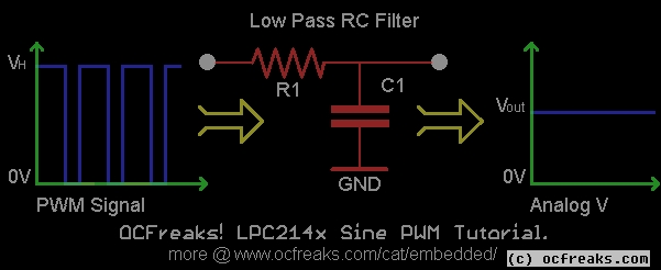
When we pass a PWM signal through a corresponding low pass filter then we get an analog voltage(or say Signal) at the output which is proportional to the dutycycle and given by:
Vout = VH x Dutycycle
Where VH is Voltage for Logic HIGH for PMW pulse. In our case its 3.3V.

Now, when we change the dutcycle i.e the T-ON time of PWM in sine fashion we get a sine waveform at the filter output. The basic idea here is to divide the waveform we want , Sine wave in our case , into ‘x’ number of divisions. For each division we have a single PWM cycle. The T-ON time or the duty cycle directly corresponds to the amplitude of the waveform in that division which is calculated using sin() function. Consider the diagram shown below :
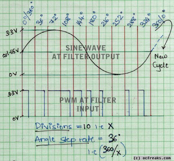

Here I’ve divided the Sine wave into 10 divisions. So here we will require 10 different PWM pulses increasing & decreasing in sinusoidal manner. A PWM pulse with 0% Duty cycle will represent the min amplitude(0V) , the one with 100% duty cycle will represent max amplitude(3.3V). Since out PWM pulse has voltage swing between 0V to 3.3V , our sine wave too will swing between 0V to 3.3V.
It takes 360 degrees for a sine wave to complete one cycle. Hence for 10 divisions we will need to increase the angle in steps of 36 degrees. This is called the Angle Step Rate or Angle Resolution.
Now we can increase the number of divisions to get more accurate waveform. But as divisions increase we also need to increase the resolution .. but we cant increase the resolution after we reach the max resolution which depends on the Processor(& Peripheral) clock.
Note : A high(i.e more Fine) Resolution in our case means that the actual value is low and vice-verse. For eg. 0.25us is a higher Resolution as compared to 1us. – This is my convention others might use it in reverse.
50 Hz Sinewave using Microcontroller based PWM
The above was just a simple example to explain the basic stuff. Now lets the actually example that I’ll be using. Here we will be generating a 50Hz Sine wave with 200 divisions.
To get the output waveform as smooth as possible we need to calculate the best possible divisions and resolution .. given we know the frequency of the output waveform. In our case will be generating a 50Hz sine wave using PWM signal generated by lpc2148 microcontroller.
Now for a 50Hz sine wave we get a period time 1/50 = 20 milliseconds which is the time required for the sine wave to complete 1 full cycle. Now our job is divide an interval of 20ms into ‘X’ divisions. Hence the number of division i.e X will decide the period of PWM signal and hence the best possible resolution can be chosen.
Now , since we will be using 200 divisions , the period of each division will be 20ms/200 = 0.1ms = 100us. This means that the period of the pwm signal will be 100us. Hence if we use a resolution of 1us then we will only have a set 100 values(actually 101 values if you consider 0 also) ranging from 1 to 100 to describe a full sine wave cycle. If we use a resolution of 0.5ms then we will have a set of 200 values. These values are the match values i.e the number of ticks of PWM counter. So if the resolution is 0.5us and period is 100 us then we will require 200 ticks to complete 100us. Similarly if resolution is 0.25us we will require 400 ticks for 100us.
This gives us the Maximum value for the match register i.e 100% Dutycycle.
NOTE: The higher this count is the more accurate the sine wave will be – given we have correspondingly high number of divisions!.
Generating the Sine lookup table
In our case since our period time is 100us we will require max 200 ticks @ 0.5us resolution. So in a lot of 200 divisions or PWM cycles the match value i.e the no.of ticks must vary from 0 to 200 in a sine fashion. This can done by finding the angle for the corresponding division. So now we must first find the angle step rate or the angle resolution , which can be given by:
In our case we get Angle step rate = 1.8 degrees. Hence the 1st division represents 0 degrees , 2nd division 1.8 degs , 3rd division 3.6 degs and so on.
Now , by multiplying the sine of angle with 50% T-ON value we can get the T-ON values for a complete cycle. But since sine gives negative values for angle between 180 and 360 we need to scale it since PWM Match values cannot be negative. Again we use 50% T-ON and add it so all values are positive. This is given by :
SineLookupTable[Y] = rint( 100 + 100 * sin( Angle_Step_Rate*Y ) );

//where Y=0,1,...X-1 & X=no.of Divisions
Note that the function “rint(..)” is used to round the computed Match Value to the nearest integer.
Using the above equation the min amplitude will be 0V(match val=0) and max 3.3V(match val=200). In order to limit the amplitude between say 0.05V(match val=1) and 3.25V(match val=199) we can modify the equation by reducing the sine scale factor from 100 to 99. So , the equation in this case will be :
SineLookupTable[Y] = rint( 100 + 99 * sin( Angle_Step_Rate*Y ) );

//where Y=0,1,...X-1 & X=no.of Divisions
Basic Digital(PWM) to Analog Filter Design
We need a Low Pass filter(LPF) which we will be using as Digital to Analog Converter i.e DAC for converting PWM into Sine. This Low Pass Filter will block the high frequency PWM signal and will let the ‘encoded’ low frequency sine wave to pass through. To design this filter , first we must decide the Cut-Off or Corner frequency. Here we can follow a rule of thumb that the cut-off frequency must be 3 to 4 times the frequency we want at the output. Since we want 50hz sine at the output we will design a simple low pass RC filter with cut-off frequency of around 200hz.


Here the Time Constant is Tc = R * C
So , from the above equation we get the equation for Time Constant as :

Now we can Find the Time Constant Tc from Fcut-off and then select appropriate values for R and C.
So , In our case with Fcut-off=200 , we get Tc=796us. Hence in our case we can select a 1.8K Resistor and a 0.47uF Capacitor which gives a Time constant of 846us.
If you don’t have R & C with those values and just want to check the Sine wave output – A Quick & Dirty method to make an RC filter for the PWM in our case can be as follows – use a resistor between 1.8K and 5.6K and a Capacitor between 0.33uF and 1uF. For example you may use a 4.7K Resistor with a 0.47uF or 1uF Capacitor.
Note : If you need more better Sine Wave you can use a Low-Pass RC or Chebyeshev Filter of Higher order.
The Sine Wave Output in Oscilloscope
Here is the output for the code(given in Source Code section below). It generates a Sine Wave having a frequency of 50Hz after filter of-course.


Here is a closeup of the Sine wave :
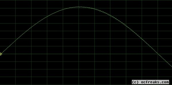

As it can be seen the Sine wave it not completely smooth since I’ve used a simple RC filter. A better Sine wave get be obtained by using a good higher order filter.
Sinewave PWM Source code
In the Code given Below First I am generating a Sine Lookup Table with 200 entries and then Setting up PWM ISR which keeps on updating the Match Value for Match Register 1 after the end of each PWM cycle. The function “initClocks()” initializes the CPU and Peripheral Clocks at 60Mhz – its code is given in attached files. [Note – The startup file i.e startup.s by itself initializes CLK and PLCK @ 60Mhz .. even then I am doing it again for those who might want to edit my code and change the clocks as required]
/*
(C) Umang Gajera | Power_user_EX - www.ocfreaks.com 2011-13.
More Embedded tutorials @ www.ocfreaks.com/cat/embedded

Source for LPC2148 Sine PWM Tutorial
License : GPL.
*/
#include <lpc214x.h>
#include <math.h>
#define PLOCK 0x00000400
#define PWMPRESCALE 30 //30 PCLK cycles to increment TC by 1 i.e 0.5 Micro-second
#define ANGLE_STEP_RATE 1.8 //i.e the Angle Resolution
#define PI 3.14159

void initPWM(void);

void initClocks(void);
void setupPLL0(void);
void feedSeq(void);
void connectPLL0(void);
void computeSineLookupTable(void);
void PWM_ISR(void) __irq;

char sineLookupTable[200];
int count=0;

int main(void)
{
	initClocks(); //Initialize CPU and Peripheral Clocks @ 60Mhz

	computeSineLookupTable(); //Compute Sine Lookup Table with 200 Divisions

	VICIntEnable |= (1<<8) ;
	VICVectCntl0 = (1<<5) | 8 ;
	VICVectAddr0 = (unsigned) PWM_ISR;

	initPWM(); //Initialize PWM

	//Sinusoidal PWM Generation is Active Now!

	while(1){}

	//return 0; //normally this wont execute ever
}

void computeSineLookupTable(void)
{
	float angle;
	int i;
	for(i=0; i<200; i++)
	{
		angle = ( ((float)i) * ANGLE_STEP_RATE );
		sineLookupTable[i] = rint(100 + 99* sin( angle * (PI/180) )); //converting angle to radians
	}
}

void PWM_ISR(void) __irq
{
	long regVal = PWMIR;

	PWMMR1 = sineLookupTable[count]; //current amplitude
	PWMLER = (1<<1); // set Latch Bit to High
	count++;
	if(count>199) count = 0;

	PWMIR = regVal; // Clear Flags
	VICVectAddr = 0xFF; //End of ISR
}

void initPWM(void)
{
	/*Assuming that PLL0 has been setup with CCLK = 60Mhz and PCLK also = 60Mhz.*/

	PINSEL0 = (1<<1); // Select PWM1 output for Pin0.0
	PWMPCR = 0x0; //Select Single Edge PWM - by default its single Edged so this line can be removed
	PWMPR = PWMPRESCALE-1; // 0.5 micro-second resolution
	PWMMR0 = 200; // 200 ticks i.e 200x0.5=100ms period duration
	PWMMR1 = 100; // Initial pulse duration i.e width
	PWMMCR = (1<<1) | (1<<0); // Reset PWMTC & Interrupt on PWMMR0 match
	PWMLER = (1<<1) | (1<<0); // update MR0 and MR1
	PWMPCR = (1<<9); // enable PWM output
	PWMTCR = (1<<1) ; //Reset PWM TC & PR

	//Now , the final moment - enable everything
	PWMTCR = (1<<0) | (1<<3); // enable counters and PWM Mode

	//PWM Generation goes active now!!
	//Now you can get the PWM output at Pin P0.0!
}
LPC2148 Development Boards that we Recommend:


