

Introduction
Whenever we want to communicate between PC and MCU or between two MCUs , the simplest way to achieve that is using UART. UART stands for Universal Asynchronous Receiver/Transmitter.
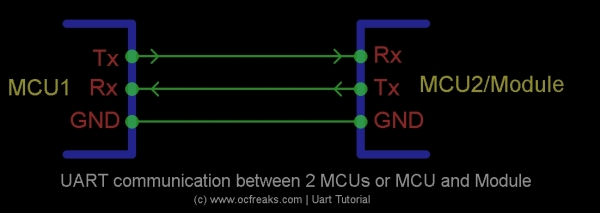
UART communication basically uses 2 pins for Data transfer and these are :
- TxD (or Tx) – which is the Transmit Data Pin used to send data
- RxD (or Rx) – which is the Receive Data Pin used to get data
UART sends & receives data in form of chunks or packets. These chunks or packets are also referred to as ‘transmission characters’. The structure of a data packets is as shown below:
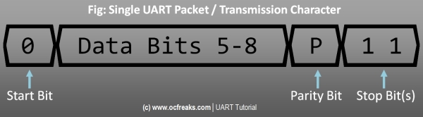

Uart data packet begins with a ‘0’. This bit is also called as “Start Bit” which signifies incoming data. Next comes the actual data which can be 5 to 8 bits in length. After the data an optional parity bit can be used for error checking. Lastly comes the “Stop Bit(s)” which is a ‘1’ and this signifies end of current data packet. Note that either 1 or 2 stop bits can be used and the parity bit can be : Even , Odd , forced to 1 i.e. Mark parity , forced to 0 i.e. Space parity or None. (In UART/RS232 context a MARK means 1 and SPACE means 0 , hence Marking state means a stream(series) of 1s and Spacing state means a stream of 0s)
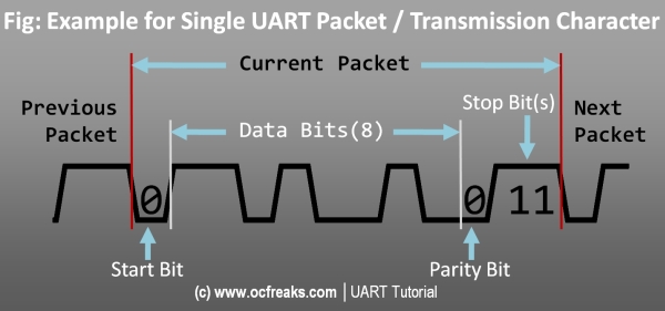
Here is an example of a packet having 8 data bits, even parity bit and 2 stop bits :

Uart connections between different MCUs , Modules and PC/Laptop


Interfacing PC or Laptop with a Microcontroller using UART
Generally these days we interface Microcontrollers like lpc1768 , lpc2148 , AVRs , PICs , etc.. using USB to Serial TTL module based on FTDI’s FT232R Chip. The first thing to take care is the voltage levels for communication. Some microcontrollers like LPC214x, LPC176x, STM32 etc.. work on 3.3 Volts and others like AVRs, etc.. work on 5V. Hence , you need to make sure that your module has appropriate voltage levels for 3.3v MCUs or 5v MCUs.
On PC/Laptop side you need a software that can communicate with your microcontroller using via Serial the communication Interface provided by your operating system. In windows this interface is named as “COMx” for e.g COM1 , COM2 , and so on. In order for terminal softwares to communicate you need to select the proper COM port. These COM port mappings can be found in device manager. Right Click “My Computer” > Click on “Manage” > and Click on “Device Manager” and you will see a window similar to what is given below :


In my case I am using a USB to Serial TTL module which is available as “COM3” in windows. Finally you need to configure your terminal software with baud rate and other information. For example, in PuttyTel this done as shown below :


You can get PuttyTel from Here. Direct download link : Here.
LPC2148 Uart Tutorial is posted @ Here , Later on LPC1768 Uart Tutorial will be posted – depends on how much time I get 😛 .. it might get delayed 🙁 .